Search the whole station
Industrial flue gas treatment has entered a new era. Traditional pollution control systems — a baghouse for dust, a wet scrubber for SO2, and a separate SCR reactor for NOx — require three distinct process stages, three footprints, three sets of operating costs, and multiple reheating steps between them. For plants operating at 200°C to 450°C, this fragmented approach means constantly cooling gas down for one process and reheating it for the next, burning fuel and money at every transition.
Ceramic fiber filter tube technology changes this equation. By combining rigid, high-temperature-resistant ceramic fiber filter elements with catalytic coatings and sorbent injection, a single filtration stage can simultaneously capture particulate matter, remove acid gases (SO2, HCl, HF), and reduce nitrogen oxides (NOx) through built-in SCR/SNCR catalytic function — all without cooling the gas stream first. This is commonly marketed as a “3-in-1” or “multi-pollutant control” ceramic filter system, and it is rapidly becoming the preferred solution for coal-fired power plants, steel sintering and pelletizing lines, cement kilns, glass furnaces, waste-to-energy incinerators, and nonferrous metal smelting operations.
Ceramic fiber filter tubes (also called ceramic filter candles, ceramic fiber filter elements, or rigid ceramic filters) are cylindrical, porous filtration media manufactured from refractory ceramic fibers — typically alumina-silicate, mullite, or aluminosilicate-based fibers — bonded into a rigid, self-supporting tube structure using inorganic binders.
Unlike flexible fabric filter bags made from woven or felted synthetic fibers (PTFE, PPS, aramid, fiberglass), ceramic fiber filter tubes are rigid, dimensionally stable candles that can withstand continuous operating temperatures from 350°C up to 900°C or higher, depending on the fiber composition and binder system. Some advanced formulations tolerate short-term excursions above 1000°C.
A typical ceramic fiber filter tube consists of:
This rigid architecture is what allows ceramic filter tubes to function simultaneously as a dust filtration medium, a catalytic reactor surface for NOx reduction, and a reaction bed for acid gas neutralization when combined with dry sorbent injection.
Ceramic fiber filter tubes (also called ceramic filter candles, ceramic fiber filter elements, or rigid ceramic filters) are cylindrical, porous filtration media manufactured from refractory ceramic fibers — typically alumina-silicate, mullite, or aluminosilicate-based fibers — bonded into a rigid, self-supporting tube structure using inorganic binders.
Unlike flexible fabric filter bags made from woven or felted synthetic fibers (PTFE, PPS, aramid, fiberglass), ceramic fiber filter tubes are rigid, dimensionally stable candles that can withstand continuous operating temperatures from 350°C up to 900°C or higher, depending on the fiber composition and binder system. Some advanced formulations tolerate short-term excursions above 1000°C.
A typical ceramic fiber filter tube consists of:
This rigid architecture is what allows ceramic filter tubes to function simultaneously as a dust filtration medium, a catalytic reactor surface for NOx reduction, and a reaction bed for acid gas neutralization when combined with dry sorbent injection.
Ceramic fiber filter tubes operate on the principle of surface filtration, similar to conventional fabric filters, but with several key advantages arising from their rigid pore structure:
Because the ceramic structure does not soften, shrink, or degrade at elevated temperature the way organic fabrics do, filtration performance remains stable even under thermal cycling and transient temperature spikes that would destroy a conventional baghouse.
Desulfurization is achieved by injecting a dry alkaline sorbent — typically hydrated lime (Ca(OH)2), sodium bicarbonate (NaHCO3), or a proprietary calcium-based reagent — into the flue gas stream upstream of the ceramic filter.
The mechanism works in two stages:
This dual-stage capture typically achieves SO2 removal efficiencies of 90-99%, depending on inlet concentration, sorbent type, calcium-to-sulfur (Ca/S) molar ratio, and residence time — all without the wastewater byproduct associated with wet flue gas desulfurization (WFGD) systems.
The denitrification function is what most distinguishes advanced ceramic fiber filter tubes from conventional dust-only systems. NOx reduction is achieved through Selective Catalytic Reduction (SCR) chemistry integrated directly into the filter element:
Because the catalyst is distributed across the entire filtration surface area of every tube — rather than concentrated in a separate downstream reactor — the effective catalyst contact area is dramatically larger than a conventional SCR honeycomb of comparable footprint. This allows NOx removal efficiencies of 80-95%+ to be achieved within the same vessel that is simultaneously removing dust and SO2, at operating temperatures as low as 180-280°C for low-temperature catalyst formulations, or 300-400°C for standard mid-temperature catalysts.
When these three mechanisms operate together in a single filter vessel, the result is often referred to as a 3-in-1 (or “one-tower”) flue gas purification system:s a dust filtration medium, a catalytic reactor surface for NOx reduction, and a reaction bed for acid gas neutralization when combined with dry sorbent injection.
Ceramic fiber filter tubes operate on the principle of surface filtration, similar to conventional fabric filters, but with several key advantages arising from their rigid pore structure:
Because the ceramic structure does not soften, shrink, or degrade at elevated temperature the way organic fabrics do, filtration performance remains stable even under thermal cycling and transient temperature spikes that would destroy a conventional baghouse.
Desulfurization is achieved by injecting a dry alkaline sorbent — typically hydrated lime (Ca(OH)2), sodium bicarbonate (NaHCO3), or a proprietary calcium-based reagent — into the flue gas stream upstream of the ceramic filter.
The mechanism works in two stages:
This dual-stage capture typically achieves SO2 removal efficiencies of 90-99%, depending on inlet concentration, sorbent type, calcium-to-sulfur (Ca/S) molar ratio, and residence time — all without the wastewater byproduct associated with wet flue gas desulfurization (WFGD) systems.
The denitrification function is what most distinguishes advanced ceramic fiber filter tubes from conventional dust-only systems. NOx reduction is achieved through Selective Catalytic Reduction (SCR) chemistry integrated directly into the filter element:
Because the catalyst is distributed across the entire filtration surface area of every tube — rather than concentrated in a separate downstream reactor — the effective catalyst contact area is dramatically larger than a conventional SCR honeycomb of comparable footprint. This allows NOx removal efficiencies of 80-95%+ to be achieved within the same vessel that is simultaneously removing dust and SO2, at operating temperatures as low as 180-280°C for low-temperature catalyst formulations, or 300-400°C for standard mid-temperature catalysts.
When these three mechanisms operate together in a single filter vessel, the result is often referred to as a 3-in-1 (or “one-tower”) flue gas purification system:s a dust filtration medium, a catalytic reactor surface for NOx reduction, and a reaction bed for acid gas neutralization when combined with dry sorbent injection.
A conventional flue gas treatment train for a coal-fired boiler or industrial furnace typically requires:
Each stage requires its own vessel, ductwork, instrumentation, and structural foundation. Combining all three functions into a single ceramic filter vessel can reduce plot space requirements by 30-50%, cut steel and civil construction costs substantially, and eliminate the reheat energy penalty entirely, since the entire process operates at the boiler’s native flue gas temperature.
Wet FGD systems generate wastewater requiring treatment and disposal, and they cool flue gas below its acid dew point, requiring reheating (via GGH or auxiliary burners) before the gas can pass through downstream SCR or exit the stack safely. Dry sorbent injection paired with ceramic filtration is a fully dry process — no wastewater stream, no reheat requirement, and no risk of visible plume formation from a saturated wet stack.
Because ceramic fiber withstands sustained operation well above the temperature limits of PTFE (260°C), PPS (190°C), or aramid (204°C) fabric filters, ceramic tubes can be installed directly downstream of the boiler or kiln outlet — often before any cooling stage — minimizing thermal cycling stress and downstream ductwork complexity. Ceramic fiber is also chemically inert to most acid gases and resistant to the abrasive, high-dust-loading conditions typical of sintering plants, cement kilns, and biomass boilers.
Rigid ceramic filter tubes typically achieve service lives of 3-5 years or longer under normal industrial operating conditions — substantially longer than typical fabric filter bag replacement intervals of 1.5-3 years in high-temperature, high-corrosivity applications. The rigid structure also resists bag collapse, pinholing, and stitching failures common to flexible filter media under thermal and mechanical stress.
Because dust, SO2, and NOx are managed within one integrated control loop, plants benefit from simplified process automation, fewer interlocks between separate systems, and — with well-designed ammonia injection grids upstream of the ceramic filter — excellent ammonia-to-NOx mixing that helps minimize ammonia slip compared to some downstream-SCR designs where mixing distance is constrained.
A conventional flue gas treatment train for a coal-fired boiler or industrial furnace typically requires:
Each stage requires its own vessel, ductwork, instrumentation, and structural foundation. Combining all three functions into a single ceramic filter vessel can reduce plot space requirements by 30-50%, cut steel and civil construction costs substantially, and eliminate the reheat energy penalty entirely, since the entire process operates at the boiler’s native flue gas temperature.
Wet FGD systems generate wastewater requiring treatment and disposal, and they cool flue gas below its acid dew point, requiring reheating (via GGH or auxiliary burners) before the gas can pass through downstream SCR or exit the stack safely. Dry sorbent injection paired with ceramic filtration is a fully dry process — no wastewater stream, no reheat requirement, and no risk of visible plume formation from a saturated wet stack.
Because ceramic fiber withstands sustained operation well above the temperature limits of PTFE (260°C), PPS (190°C), or aramid (204°C) fabric filters, ceramic tubes can be installed directly downstream of the boiler or kiln outlet — often before any cooling stage — minimizing thermal cycling stress and downstream ductwork complexity. Ceramic fiber is also chemically inert to most acid gases and resistant to the abrasive, high-dust-loading conditions typical of sintering plants, cement kilns, and biomass boilers.
Rigid ceramic filter tubes typically achieve service lives of 3-5 years or longer under normal industrial operating conditions — substantially longer than typical fabric filter bag replacement intervals of 1.5-3 years in high-temperature, high-corrosivity applications. The rigid structure also resists bag collapse, pinholing, and stitching failures common to flexible filter media under thermal and mechanical stress.
Because dust, SO2, and NOx are managed within one integrated control loop, plants benefit from simplified process automation, fewer interlocks between separate systems, and — with well-designed ammonia injection grids upstream of the ceramic filter — excellent ammonia-to-NOx mixing that helps minimize ammonia slip compared to some downstream-SCR designs where mixing distance is constrained.
Ceramic fiber filter tube systems have been successfully deployed across a wide range of high-temperature industrial processes:
Ultra-low emission retrofits for utility and industrial boilers, replacing or complementing ESP + WFGD + SCR trains with a compact single-tower solution, particularly attractive for space-constrained retrofit projects.
Sintering machine and pelletizing plant off-gas treatment, where high dust loading, SO2, and NOx must be controlled simultaneously; also applicable to electric arc furnace (EAF) and blast furnace gas cleaning.
Kiln tail gas and raw mill exhaust treatment, addressing dust, SO2, and NOx in a single stage while tolerating the alkaline, high-temperature, high-dust conditions typical of cement production.
Combined control of dust, acid gases (SO2, HCl, HF), NOx, and — with activated carbon co-injection — dioxins, furans, and heavy metals (mercury) in one integrated system, well suited to the strict multi-pollutant limits governing incineration facilities.
High-temperature furnace exhaust treatment where dust and SO2 control are required at elevated, sustained temperatures unsuitable for conventional bag filters.
Copper, lead, zinc, and other smelting operations with corrosive, high-temperature off-gas streams requiring robust filtration media resistant to chemical attack.
Various high-temperature process off-gas streams requiring combined particulate and acid gas control ahead of downstream processing or emission to atmosphere.
 ceramicfiber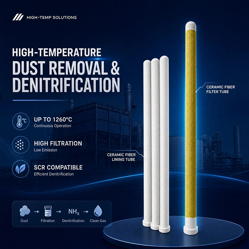

提交产品咨询
我们将会在24小时内联系您