Search the whole station
Tube furnaces are the workhorses of laboratories, universities, and advanced materials production lines — used every day for CVD, annealing, sintering, calcination, crystal growth, catalyst research, and battery material development. And every tube furnace, whether a compact single-zone lab unit or a three-zone production system, depends on one critical component: the cylindrical ceramic fiber heating chamber that surrounds the work tube.
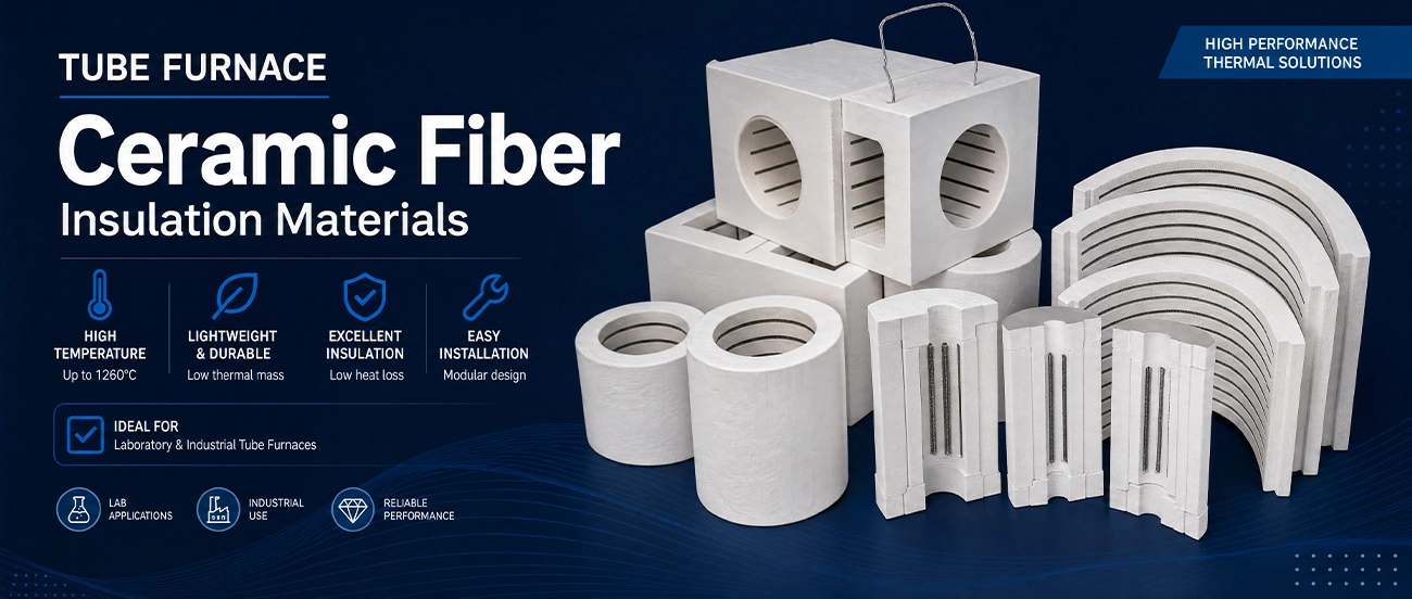
We design and manufacture the complete range of ceramic fiber insulation for tube furnace construction: one-piece vacuum-formed cylindrical chambers, split half-shell (clamshell) heaters with integral element grooves, embedded-element heating modules, end plugs and tube seals, multi-zone lining assemblies, and machined special shapes — every product fully customizable to your bore diameter, heated length, temperature rating, and element layout.
Temperature grades from 1260°C to 1700°C. Bore diameters from 25 mm to 600 mm+. Single-zone and multi-zone designs. Elements embedded or grooved to your drawing. Low MOQ for prototypes and rebuilds, full OEM production support.
If you build tube furnaces, rebuild them, or need a replacement heating chamber for an existing unit, this page covers everything you need to specify the right insulation — and how our custom manufacturing process works.

Older tube furnace designs used ceramic fiber blanket wrapped by hand around a coiled element, or dense refractory sleeves. Both approaches have been almost entirely replaced by vacuum-formed rigid ceramic fiber chambers, and the reasons are fundamental to tube furnace performance:
Temperature uniformity along the heated zone is the defining specification of a tube furnace. A vacuum-formed cylinder with machined or molded helical grooves holds the resistance wire at an exact, repeatable pitch — including graded (variable-pitch) winding that compensates for end losses and extends the uniform zone. Hand-wrapped blanket simply cannot achieve this. With formed chambers, uniformity zones of ±1°C to ±5°C become manufacturable at scale.
Vacuum-formed fiber bodies (typically 250–400 kg/m³) store very little heat. Lab tube furnaces built on our chambers routinely ramp at 10–40°C/min and cool quickly between runs — essential for research throughput and for processes like RTP-style annealing where cycle time matters.
Thermal conductivity of 0.10–0.20 W/m·K at operating temperature means a compact insulation package delivers a cool outer shell. This allows the slim, lightweight furnace housings the market expects — a 1200°C lab tube furnace with a shell you can rest your hand near — while cutting power consumption 30–50% versus dense refractory designs.
Tube furnaces are cycled constantly: room temperature to 1000°C+ and back, sometimes several times a day. The flexible fiber matrix absorbs this stress without the spalling and cracking that destroys rigid refractories, giving multi-year lining life in cyclic service.
Vacuum forming produces either a seamless full cylinder (for fixed-tube furnaces where the work tube slides in) or matched half-shells for split / clamshell / hinged furnace designs that open around the tube. Both come out of the mold with grooves, lead-out holes, and thermocouple ports already in place.
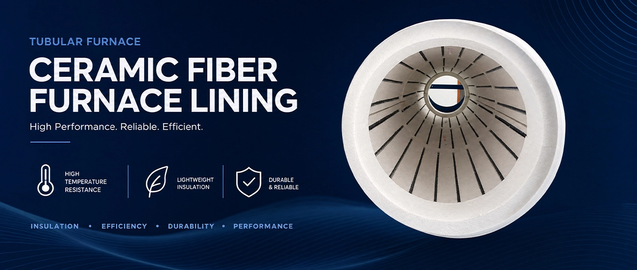
A complete tube furnace lining is a system, not a single part. We supply every component, individually or as a fitted kit:
The core of fixed-bore tube furnaces. A seamless rigid cylinder with:
Matched pairs of semi-cylindrical vacuum-formed shells for split tube furnaces — the hinged designs that open to load reactors, quartz tubes with fittings, or oversized workpieces without disturbing end connections.
For OEMs who want a drop-in solution: chambers or half-shells supplied with FeCrAl (Kanthal-type) or NiCr resistance coils cast/embedded into the fiber body or installed in grooves, terminals positioned per your drawing, resistance value tested and documented per unit. You mount, wire, and ship. For higher temperatures we supply chambers designed around SiC rods (to ~1400–1500°C) and MoSi₂ elements (to ~1700–1800°C element temperature) with formed element pass-through holes, support cutouts, and radiation baffles.
End losses ruin uniformity and waste energy. We manufacture:
Two-, three-, and five-zone tube furnaces need separately controlled winding sections with insulating barrier rings between zones. We supply complete multi-zone chamber sets — grooved sections, zone-separation discs, and thermocouple porting per zone — engineered as one assembly so zones align perfectly on your center line.
Support saddles for heavy work tubes, element carrier rings, radiation shields, gas-inlet blocks, viewport sleeves — any geometry, formed or CNC-machined from board and billet.
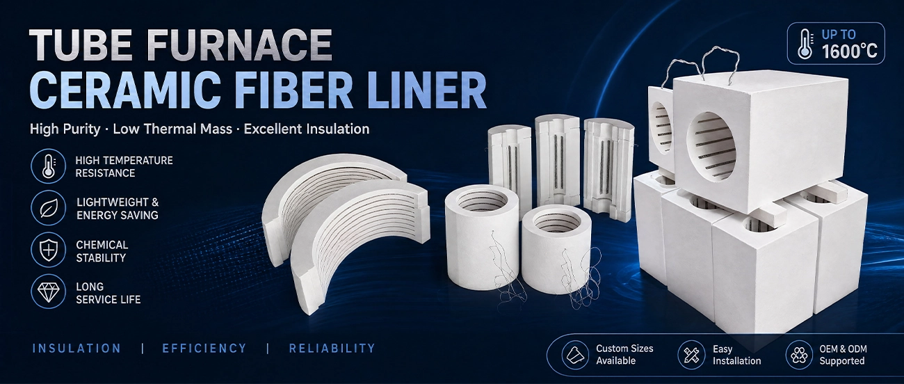
Standard catalog cylinders force your furnace design into someone else’s dimensions. We work the other way around — every chamber is manufactured to your specification, which is why OEM tube furnace manufacturers, rebuilders, and research labs worldwide source from us.
1. Bore, Length, and Wall Thickness Any bore from 25 mm to 600 mm+; heated lengths to 2000 mm (jointed sections beyond); wall thickness engineered from your target shell temperature and housing diameter. Concentricity and bore tolerance controlled for consistent tube-to-element gap — critical for uniformity.
2. Element Groove Design
3. Zones and Sensors Multi-zone segmentation, zone barrier rings, control and over-temp thermocouple ports at exact axial/radial positions — formed in, never field-drilled.
4. Construction Style Full cylinder, split halves, hinged-clamshell pairs, or segmented multi-piece designs for very large bores. Stepped mating joints available on all split designs.
5. Density, Hardness & Surface Standard or high-density bodies; rigidized bores; coated surfaces for particulate atmospheres; low-organic formulations for clean processes.
6. Complete Kits and Heating Modules Chamber + end plugs + backup blanket + board end walls + shell gaskets, delivered as a numbered kit with an assembly drawing — or the fully embedded-element module, resistance-tested, ready to drop into your housing.
Low MOQ means we’re practical for one-off replacement chambers, university lab rebuilds, and R&D prototypes — not just volume OEM programs. We regularly reverse-engineer heating chambers for discontinued tube furnace models from photos and measurements. gas-inlet blocks, viewport sleeves — any geometry, formed or CNC-machined from board and billet.
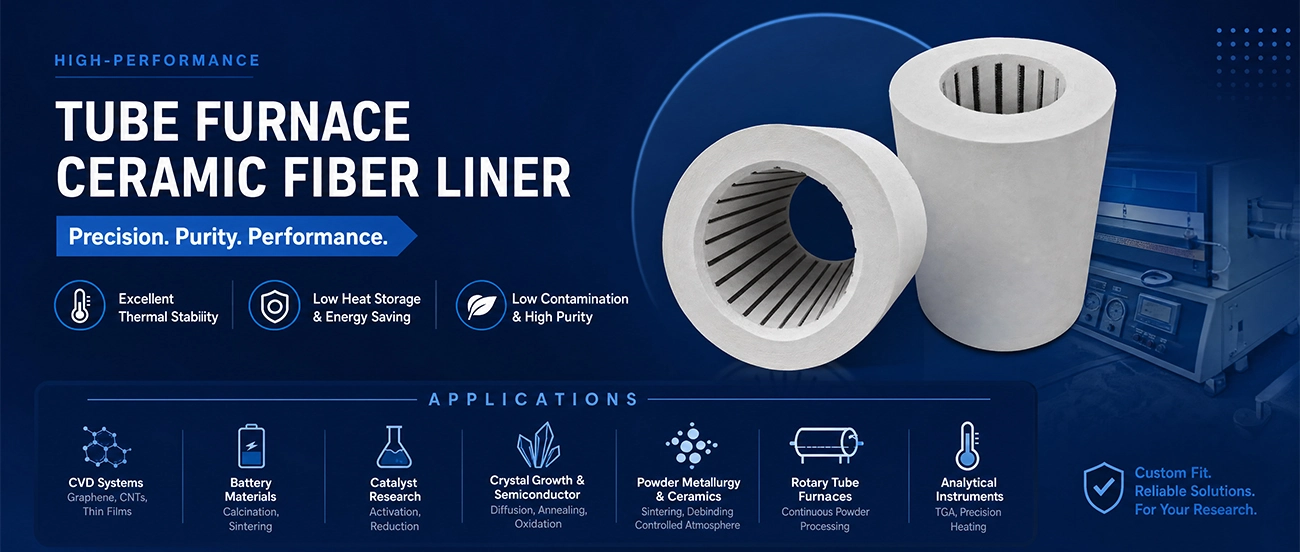
Furnace rebuilds — replacement chambers for aging or failed heating modules of most common laboratory brands
Laboratory tube furnaces — single-, dual-, and three-zone research furnaces, horizontal and vertical
CVD systems — chemical vapor deposition of graphene, carbon nanotubes, thin films
Battery materials — cathode/anode powder calcination in rotary and static tube furnaces, atmosphere-controlled sintering
Catalyst research — activation, reduction, temperature-programmed reactions
Crystal growth & semiconductor processing — diffusion, oxidation, annealing (low-contamination polycrystalline grades)
Powder metallurgy & technical ceramics — sintering, debinding under controlled atmosphere
Rotary tube furnaces — heating chambers for continuous powder processing
Thermogravimetric and analytical instruments — compact precision heater chambers
| Ceramic Fiber Heating Module | XMF-1100 | XMF-1200 | XMF-1300 | XMF-1400 | XMF-1500 | XMF-1600 | |
| Working Temperature(℃) | 1100 | 1200 | 1350 | 1500 | 1600 | 1700 | |
| Density(kg/m³) | 300-600 | 300-600 | 300-600 | 300-600 | 450-700 | 450-700 | |
| Linear Shrinkage(24H) (After Burning) (%) | ≤3.0 (1100℃) | ≤3.0 (1250℃) | ≤3.0 (1300℃) | ≤1.0 (1450℃) | ≤1.0 (1550℃) | ≤1.0 (1650℃) | |
| Thermal Conductivty Rate (W/m.k) | 400℃ | 0.084 | 0.084 | 0.084 | / | / | / |
| 800℃ | 0.128 | 0.125 | 0.125 | 0.160 | 0.160 | 0.160 | |
| 1000℃ | 0.176 | 0.174 | 0.200 | 0.210 | 0.210 | 0.210 | |
| Heating Element | Resistance wire | SiC heating element | SiC heating element | MoSi2 heating element | MoSi2 heating element | MoSi2 heating element | |
| Furnace Chamber Size | Customized | Customized | Customized | Customized | Customized | Customized | |
| The sizes and packaging can be customized according to your needs | |||||||
Get Started Free Call?
TEL: +86 1234567
E-mail: info@xxx.com
Detailed disassembly video
Yes. Send the old chamber, or photos plus bore diameter, heated length, overall length, groove pitch, and lead-out positions. We reverse-engineer replacements for most common lab furnace brands, including embedded-element versions.
Full cylinders give the best uniformity and lowest cost for fixed-tube designs where the work tube slides in and out. Split half-shells are essential for hinged/clamshell furnaces that must open around a tube with fixed end fittings (CVD reactors, sealed quartz systems). We supply both; if your housing design is still open, we’ll advise.
Three tools working together: graded element winding pitch (tighter at the ends), properly sized end plugs/baffles, and adequate wall thickness. Tell us your required uniform zone length and tolerance (e.g. ±5°C over 300 mm) and we’ll engineer the groove layout to hit it.
Typically up to ~1000–1200 mm as a single forming, depending on bore. Longer heated lengths are supplied as matched, stepped-joint sections that align on assembly — standard practice in multi-zone production furnaces.
The fiber chamber normally sits outside the sealed work tube, so furnace atmosphere rarely contacts it. For retort designs where insulation sees the process atmosphere, we’ll recommend grades and treatments accordingly — reducing atmospheres and water vapor affect fiber life and must be factored in.
 ceramicfiber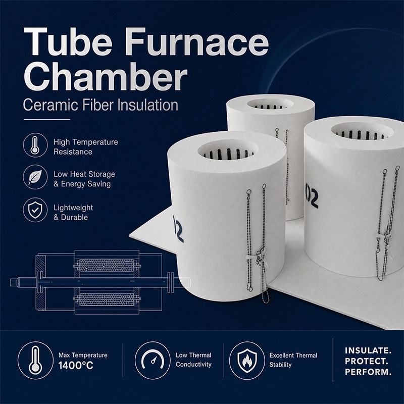

提交产品咨询
我们将会在24小时内联系您